Compare Low Voltage Systems: The Definitive Editorial Guide
Compare low voltage systems the architectural and infrastructural integrity of a modern property is increasingly defined by the invisible networks that facilitate communication, lighting, and power distribution. While the primary electrical grid provides the brute force necessary for heavy appliances and climate control, the nuanced layers of an estate—security, automated illumination, and high-fidelity audio—operate within the domain of low-voltage technology. Navigating this landscape requires more than a cursory glance at product specifications; it demands an analytical understanding of how different electrical architectures interact with environmental stressors and user expectations.
To approach a project with professional rigor, one must look beyond the initial convenience of “plug-and-play” solutions. The decision to implement a specific low-voltage standard affects everything from the long-term maintenance overhead to the structural resilience of the building envelope. In North America, where safety codes and energy efficiency mandates are in constant flux, the ability to discern between competing systems is a critical skill for architects, developers, and discerning homeowners alike.
This editorial deconstruction moves away from the simplified marketing narratives that often cloud the industry. Instead, we focus on the physics of power delivery, the reliability of signal transmission, and the fiscal realities of deployment. By establishing a definitive reference for these systems, we provide the groundwork for infrastructure that is not only functional today but adaptable to the technological shifts of the next two decades.
Understanding “compare low voltage systems”
To effectively compare low voltage systems, one must first establish a baseline for what constitutes “low voltage” in different contexts. In the realm of landscape lighting and small-scale residential automation, we are typically discussing 12V to 24V DC or AC circuits. However, in the broader context of Power over Ethernet (PoE) and smart building infrastructure, “low voltage” can extend up to the 48V–60V range. The central challenge in any comparison is not just the numerical voltage, but the “Voltage Drop”—the loss of electrical potential as current travels through a conductor.
A multi-perspective analysis requires examining the “Current Density” and “Signal-to-Noise Ratio” across different architectures. For instance, comparing a traditional 12V AC landscape system to a modern 24V DC digital system reveals a fundamental trade-off: the 12V system is more forgiving of minor wiring imperfections but suffers significantly more from dimming and color shift at the end of a long wire run. Conversely, 24V systems allow for longer distances and thinner gauges of copper, but they require higher-quality drivers and more precise surge protection to prevent catastrophic failure of integrated LED chips.
The oversimplification risk here is treating all low-voltage hardware as interchangeable. A common error is assuming that a system designed for indoor smart lighting can be adapted for a coastal exterior environment simply by changing the housing. The reality is that the “Resistance Profile” of the system changes based on ambient temperature, moisture ingress, and the chemical composition of the soil or air. A master-level comparison evaluates the “Systemic Robustness”—how well the control logic and the physical hardware withstand the specific environmental stressors of the site.
Historical and Systemic Evolution of Electrical Distribution
Compare low voltage systems the trajectory of low-voltage power has transitioned from “Analog Simplicity” to “Digital Orchestration.” The Early Incandescent Era (1960s–1980s) relied on line-voltage (120V) for almost everything. This was inherently dangerous in outdoor settings and required heavy, expensive conduit. The shift to low-voltage was initially a safety-driven move, facilitated by the mass production of the magnetic transformer.
The Halogen and Magnetic Era (1990s–2000s) was the heyday of 12V AC. These systems were robust but inefficient. They generated massive heat and were limited by the “Halogen Cycle,” which required bulbs to run at specific temperatures to remain functional. During this time, the primary struggle for installers was “Balancing the Load”—ensuring that every light on a circuit received roughly the same voltage to prevent premature bulb failure.
Today, we occupy the Solid-State and Networked Epoch. We have moved beyond merely delivering power; we are now delivering data alongside current. Whether through DMX protocols, Zigbee mesh networks, or hardwired PoE, modern systems are essentially specialized computers. The evolution has moved the complexity from the “Brute Force” of the wire gauge into the “Precision” of the electronic driver and the software logic that governs it.
Conceptual Frameworks and Mental Models Compare Low Voltage Systems
Professional integrators utilize specific mental models to diagnose and design these systems before a single trench is dug.
1. The “Capillary Ingress” Model
This framework views every wire as a potential straw. If a wire jacket is nicked, water can be “wicked” up the copper strands through capillary action, eventually reaching the transformer or the LED board and causing a systemic short. Comparing systems involves looking at the quality of the “Potting”—the resin that seals the electronics—to see how well it resists this wicking effect.
2. The “Thermal Budget” Framework
Every low-voltage component has a limited capacity to dissipate heat. In high-performance systems, the heat isn’t generated by the light source alone, but by the “Driver” that converts power. A system with a superior thermal budget uses aluminum heat-sinking rather than plastic, ensuring that the internal components don’t “drift” in color or intensity as they warm up.
3. The “Signal-Power Paradox”
This model addresses the conflict between sending power and sending data over the same wire. As you increase the power load (voltage/amperage), you create electromagnetic interference that can “drown out” the digital signal. Comparing systems requires evaluating their “Shielding” and “Packet Resilience”—how well the smart features work when the lights are at full brightness.
Key Categories and Technical Variations
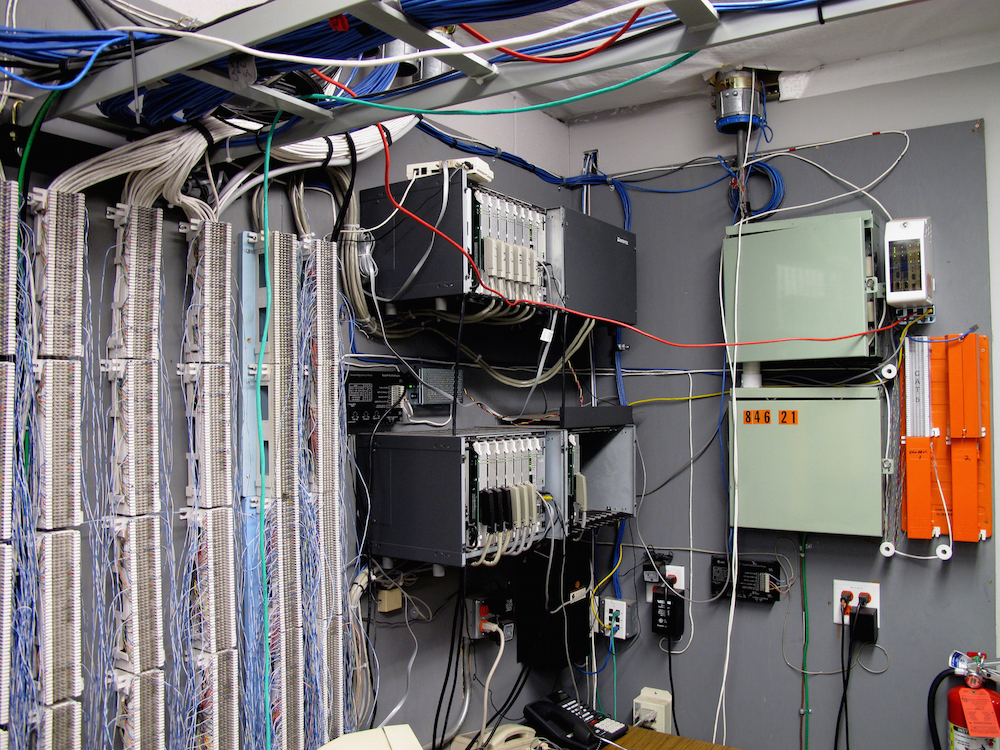
When you compare low voltage systems, the hardware typically falls into several distinct technical tiers based on their power delivery and control logic.
The decision logic here is often dictated by the “Density of Endpoints.” In a high-density environment, such as a modern office or a luxury estate with 200+ lighting nodes, a PoE or 24V Digital system is almost always the more cost-effective choice in the long run because it reduces the amount of copper required and simplifies the “Head-End” (the central control hub).
Detailed Real-World Scenarios Compare Low Voltage Systems and Decision Logic
The Coastal Luxury Estate
-
The Conflict: High salinity, extreme moisture, and a need for “Warm Dimming” (light that gets warmer as it dims).
-
The Strategy: A 24V DC system with “Solid Brass” fixtures and “Fully Potted” drivers.
-
The Logic: 12V would suffer too much from the long runs required for a large estate. The solid brass resists corrosion, and the 24V architecture allows for the sophisticated drivers needed for warm-dimming synchronization.
-
Result: A resilient, theater-quality atmosphere that survives the salt air.
The Smart High-Rise Retrofit
-
The Conflict: Rigid concrete structures make running new high-voltage conduit impossible.
-
The Strategy: A PoE (Power over Ethernet) lighting network.
-
The Logic: Low-voltage Cat6 cable can be run in existing low-profile cavities without the need for a licensed electrician to bend conduit. The IP-based control allows every light to be an individual data point for energy tracking.
-
Result: A 40% reduction in installation labor and a 100% addressable lighting grid.
Planning, Cost, and Resource Dynamics Compare Low Voltage Systems
The economic profile of these systems is a study in “Front-Loaded Capital” versus “Operational Maintenance.”
The “Opportunity Cost” of choosing an analog 12V system today is the loss of “Future-Proofing.” Within 10 years, many analog components will be “Legacy Tech,” making it difficult to find replacement parts or integrate with the next generation of smart home AI. Spending an extra 20% on a digital 24V backbone today is a hedge against a total system overhaul in a decade.
Tools, Strategies, and Support Systems Compare Low Voltage Systems
-
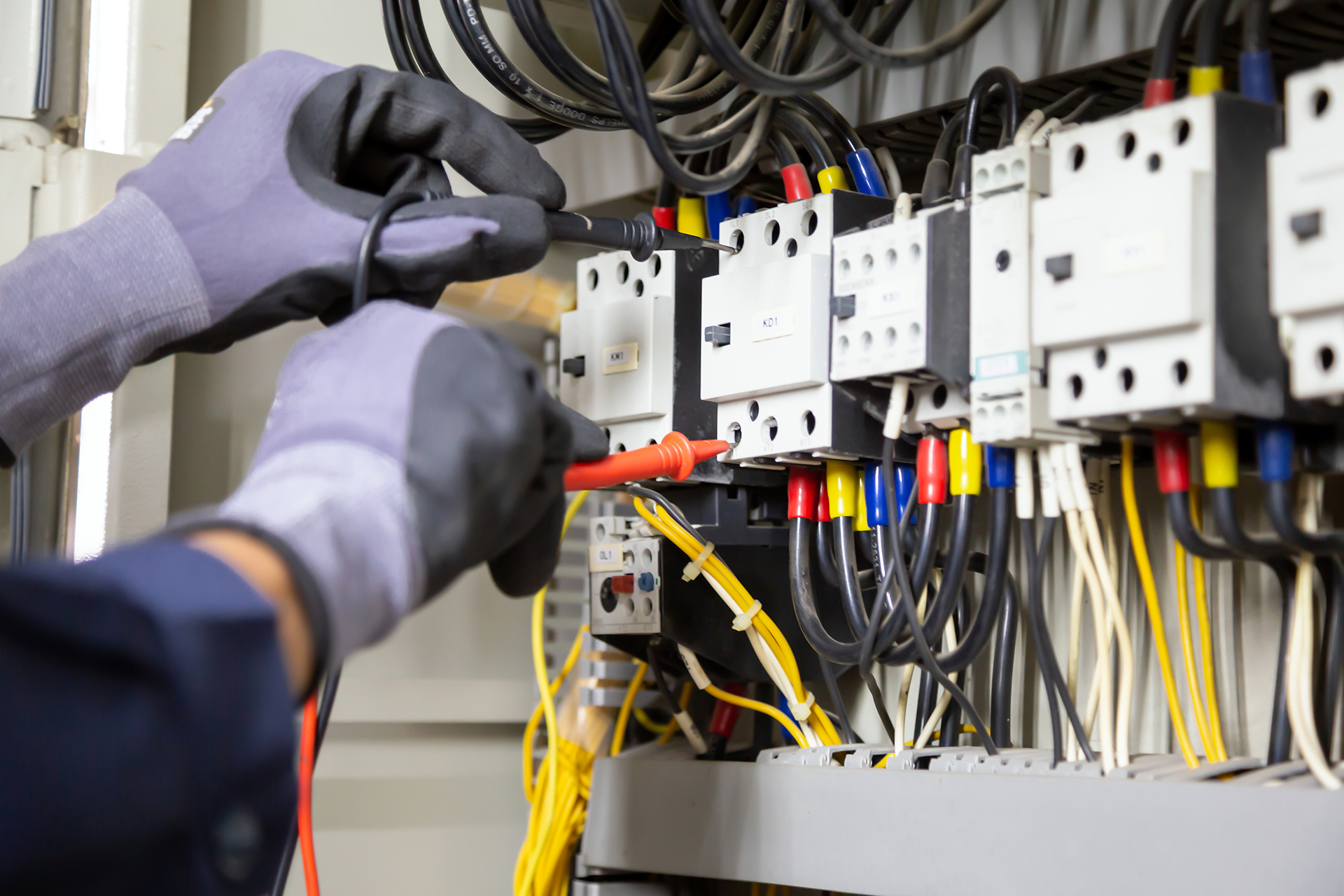
Multi-Tap Transformers: Essential for traditional AC systems, allowing the technician to select a higher output voltage (e.g., 14V or 15V) at the source to compensate for the drop at the end of the line.
-
Digital Oscilloscopes: Used in high-end digital system diagnostics to ensure that the “Data Packets” are reaching the lights without interference.
-
Heat-Shrink Solder Connectors: The only professional-grade way to join wires in a low-voltage environment; wire nuts and tape are the primary causes of system failure over time.
-
Lux Meters and Spectrometers: Tools to verify that the color temperature (Kelvin) and intensity (Foot-candles) are consistent across different circuits.
-
Surge Protection Devices (SPDs): Critical for DC and Digital systems, which are significantly more sensitive to lightning or utility surges than old magnetic systems.
-
Load Calculators: Software that prevents “Transformer Overload” by accounting for the “Inrush Current” (the spike of power needed when a system first turns on).
Risk Landscape and Failure Taxonomy Compare Low Voltage Systems
Identifying the failure modes is critical to an effective compare low voltage systems analysis.
-
Type I: The “Floating Neutral” Failure. Occurs when a return wire is loose, causing erratic voltage spikes that can fry sensitive LED drivers.
-
Type II: Galvanic Corrosion. When two different metals (e.g., a copper wire and an aluminum connector) touch in a moist environment, they create a “Battery Effect” that eats away the metal, leading to a high-resistance junction.
-
Type III: LED “Droop.” A phenomenon where the LED efficiency decreases over time due to poor heat-sinking, leading to a permanent loss of brightness.
-
Type IV: Signal Ghosting. In digital systems, where a command is sent but the light “flickers” or ignores it due to electromagnetic interference (EMI) from a nearby high-voltage line.
Governance, Maintenance, and Long-Term Adaptation
A low-voltage system is a “Living Asset.” It requires a “Governance Cycle” to ensure the investment is not lost to the elements.
The Maintenance Protocol:
-
Quarterly: Inspect “In-Grade” fixtures for debris. Soil and leaves can trap heat, significantly shortening the life of an LED driver.
-
Bi-Annually: Check the “Voltage at the Node.” If a 12V light is only receiving 10.5V, it will start to shift in color and die prematurely.
-
Annually: “Re-torque” all transformer lugs. Thermal expansion and contraction loosen mechanical connections over time, creating “Hot Spots” in the panel.
-
Software Review: For digital/PoE systems, ensuring that firmware is updated to patch security vulnerabilities in the gateway.
Measurement, Tracking, and Evaluation Compare Low Voltage Systems
How do we measure the success of an installation?
-
Leading Indicator: “Voltage Consistency.” The goal is a variance of less than 5% between the first and last fixture on a run.
-
Lagging Indicator: “Mean Time Between Failures (MTBF).” If a system requires more than one service visit per year, the design logic is likely flawed.
-
Qualitative Signal: “Visual Uniformity.” Standing at a distance, do all 3000K lights actually look 3000K? A mismatch indicates a power delivery issue or a poor “Binning” process by the manufacturer.
Common Misconceptions and Strategic Errors
-
“Low voltage means it’s totally safe.” While it won’t stop a human heart like 120V can, low voltage can still generate extreme heat. A short in a high-amperage 12V line can easily start a fire in dry mulch.
-
“I can use the same wire for everything.” High-speed digital signals require specific “Twisted Pair” or shielded cabling; using standard burial wire for a DMX signal will result in constant flickering.
-
“Voltage drop doesn’t matter for LEDs.” Most LEDs have a “minimum threshold.” If you drop below 9V, the light doesn’t just get dimmer; it shuts off or flickers uncontrollably.
-
“Solar is a professional alternative.” Solar is a utility, not a system. In a professional compare low voltage systems context, solar is only used for remote “Islands” where trenching is physically impossible.
-
“Wattage is the same as brightness.” In the LED world, “Lumens” matter. A 5-watt high-efficiency chip can be twice as bright as a 5-watt cheap chip.
Ethical and Practical Considerations Compare Low Voltage Systems
In the context of the “Dark Sky” initiative and global energy conservation, the move toward low-voltage is an ethical choice. We have a responsibility to design systems that reduce “Sky Glow” and respect the circadian rhythms of local wildlife. A well-designed low-voltage grid is not just a luxury; it is a tool for ecological stewardship.
Conclusion
The architecture of power is a balance between the physical limitations of copper and the digital potential of software. To master the ability to compare low voltage systems is to recognize that the “Best” system is the one that aligns with the “Operational Reality” of the site. It requires the technical depth to calculate voltage drop, the editorial judgment to prioritize longevity over flashy features, and the adaptability to plan for a future where every light is a node on a network. By building on a robust, low-voltage foundation, we transform a static building into a responsive, resilient environment.